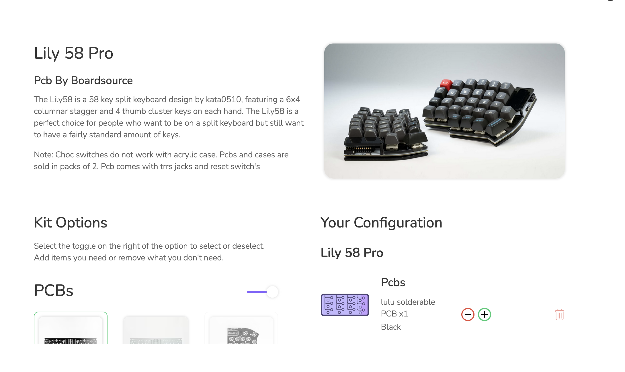
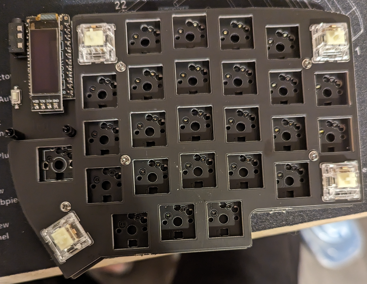
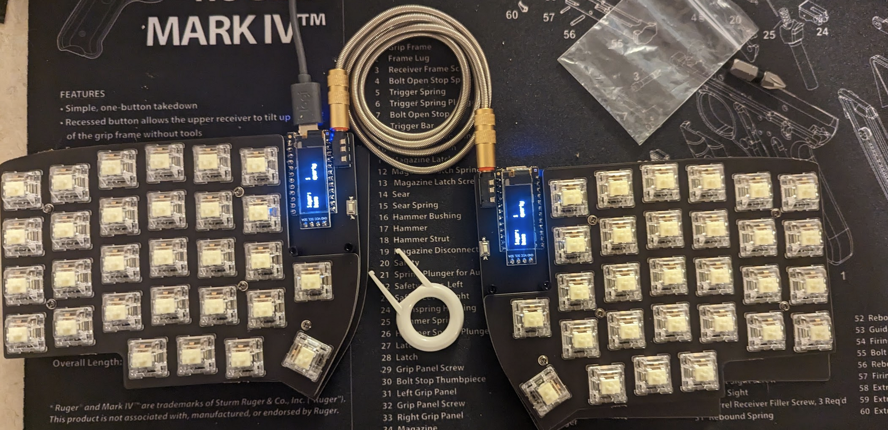
The Lily 58 Pro is a split keyboard with a 6x4 column stagger and 4 key thumb clusters. It was originally designed by kata0510 and is one of the more popular layouts for diy split keyboards, especially among newcomers - like me! This is my first keyboard build, so I needed something that was fairly easy to build and is well supported in the community. Luckily the Boardsource.xyz store has a kit just for this which helped to make sure I had all the necessary components! For those who are not interested in doing quite a bit of soldering you can also pay for it to come pre-soldered.
Despite lots of help from various community guides, as well as some direct help from the great people in the Boardsource discord, I still ran into some issues. So I decided to write this guide to aggregate information from all the sources I used, document the issues I ran into, and hopefully help someone new who is trying to get into the hobby!
Part 1: Ordering Components
There are several configurable options when purchasing this kit, so I’ll list everything and explain why I chose the parts that I did. It’s important to note that the kit does not include everything you need to assemble the keyboard completely, so I’ll include a list of additional components and equipment needed at the end.
PCBS
1x Lulu solderable PCB - Black, White, Red, or Yellow
This is the core component of the keyboard, it’s what everything gets soldered to. Note this is not the Lily58 Pro PCB, it’s Boardsource’s board that is the same layout as the Lily58 Pro, which can lead to some confusion when trying to use Lily58 Pro specific guides and resources.
Cases
1x Case - FR4 Black, FR4 White, FR4 Yellow, Clear Acrylic, or Smoke Acrylic
I chose Black FR4 here because it was the cheapest.
Cables
Lots of choices here, you need 1x TRRS cable for connecting the two halves of the keyboard and 1x USB-C cable for connecting the keyboard to the computer.
I chose the silver TRRS cable and didn’t order a USB-C cable because I already had one.
Sockets
Options: MX Hot Swap Sockets (Black or White) or Choc Hot Swap Sockets
Be sure to get whichever sockets needed to fit the switches you want to use. I bought Durock L1 Linear switches, which are an MX style switch. So I got the MX Hot Swap Sockets.
These come in strips of 10 and 6 strips will be automatically added to the cart because this keyboard has 56 keys.
Diodes
Only one option here. Same situation as the sockets, you’ll get 60 of them.
OLED Screen
While not required, this screen is really nice for troubleshooting if you have any issues with your keyboard. The screen will display some basic information about the state that the keyboard is in.
Microcontroller
There are two options here: Blok and Elite-C.
I got the Blok because it was the default option. I also really like it because it works with Boardsource’s Peg firmware utility.
Switches
Boardsource has lots of options here, so choose whichever switch you prefer as long as it matches the sockets you selected. You can also order the switches from somewhere other than Boardsource if you desire, this is what I did.
I personally love linear style switches and I bought Durock L1s. After having used the keyboard for several weeks I’ve found myself wishing that I had bought the L2s because the L1 key press weight is slightly too light for me, I find myself accidentally pressing keys often.
Not Included in the kit
There are several other items you’ll need to complete the build, I’ve listed them here.
Key Caps
Before you can type on your keyboard you’ll need to put key caps on the switches. Choose whatever you like here, there are lots of options. I recommend ensuring that the key caps include at least a few that are blank or have a custom symbol on them to go on the GUI and keyboard function keys.
Soldering Equipment
I recommend getting a soldering iron that has a digital readout for adjusting the temperature and that goes up to at least 700 degrees. I have the SainSmart station from Amazon.
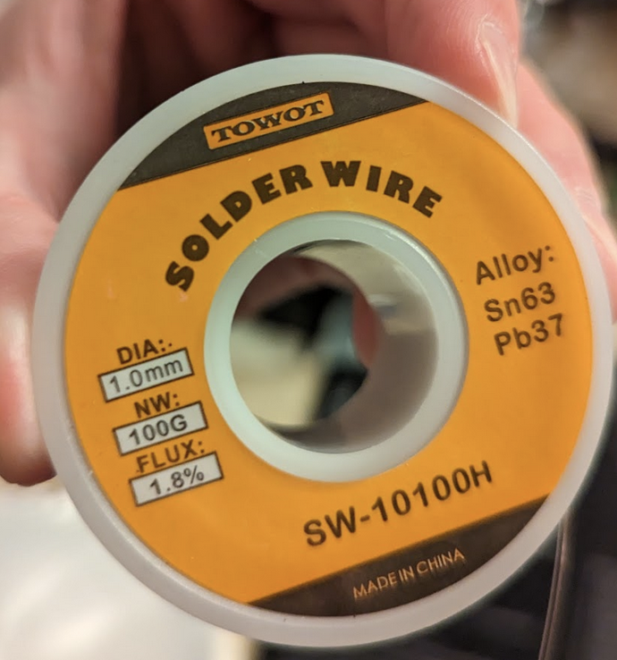
You will also want high purity lead solder with flux. This will make flowing solder on small components significantly easier.
Tweezers Any fairly small pair of tweezers will do, they are absolutely necessary to hold the smaller parts while soldering.
Masking Tape You’ll want masking tape handy to hold some components in place when you flip over the board to solder them.
Part 2: Unboxing and Prepping Workspace
Your kit will come in a box with a lot of small pieces. For this reason I recommend setting aside a dedicated workspace where all of your equipment will be undisturbed for the duration of the build and I recommend using some kind of mat underneath where you’re working so that any small pieces you drop don’t bounce too far. You’ll see in my pics that I’m using a Ruger Mk 1 breakdown mat, but it’s the same material as a mouse pad so any old mat will work just fine.
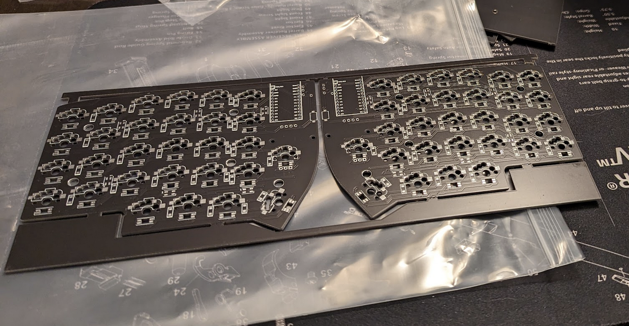
Once you have your workspace set up, the next step is to open everything up and cut out the PCBs. I used a pair of pliers to break the extra material off the PCBs here, you’ll want to be somewhat cautious here because the PCB material is fiberglass and could cut you.
Part 3: Soldering Diodes and Key Sockets
Recommended practice for soldering these components is to set your soldering iron to 650 degress fahrenheit, heat the pad on the PCB for ~2-3 seconds, and flow a small amount of solder on the pad for one side of the component. Then hold the component with tweezers, heat the contact on the component for ~2-3 seconds and press it into the solder on the pad. Now that the solder is holding the component in place on one side you can easily solder the other side to the board.
Note: It is important to not hold the soldering iron on the PCB or the component for too long or you may burn it. If it gets burned too badly it’s possible to ruin the component.
As you’ll see in the pictures of my build, I am pretty new to soldering delicate electrical components. A lot of the advice I’ve given here is from youtube videos I watched or advice I got from an Electrical Engineer friend when troubleshooting why things weren’t working after finishing the initial build.
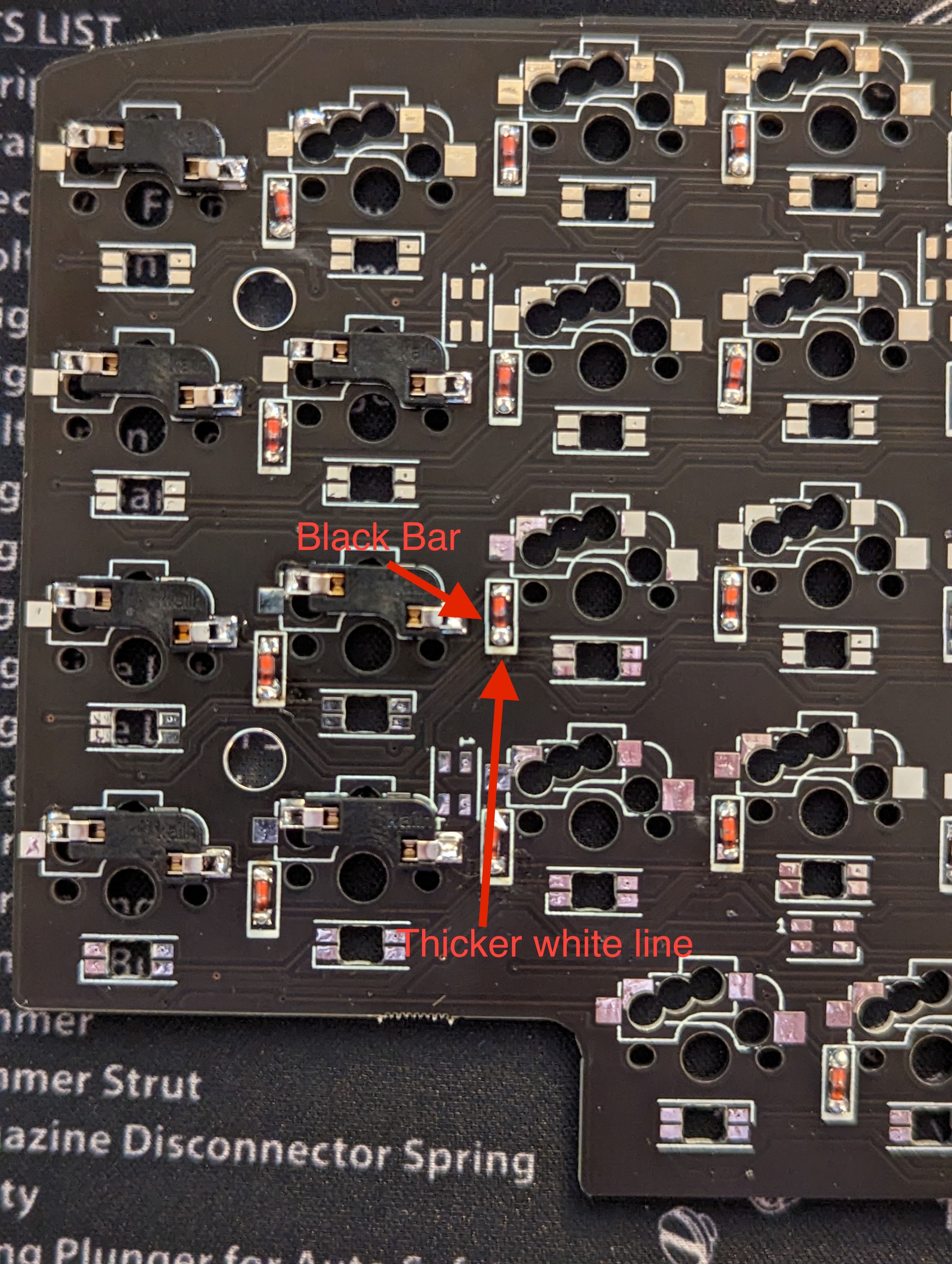
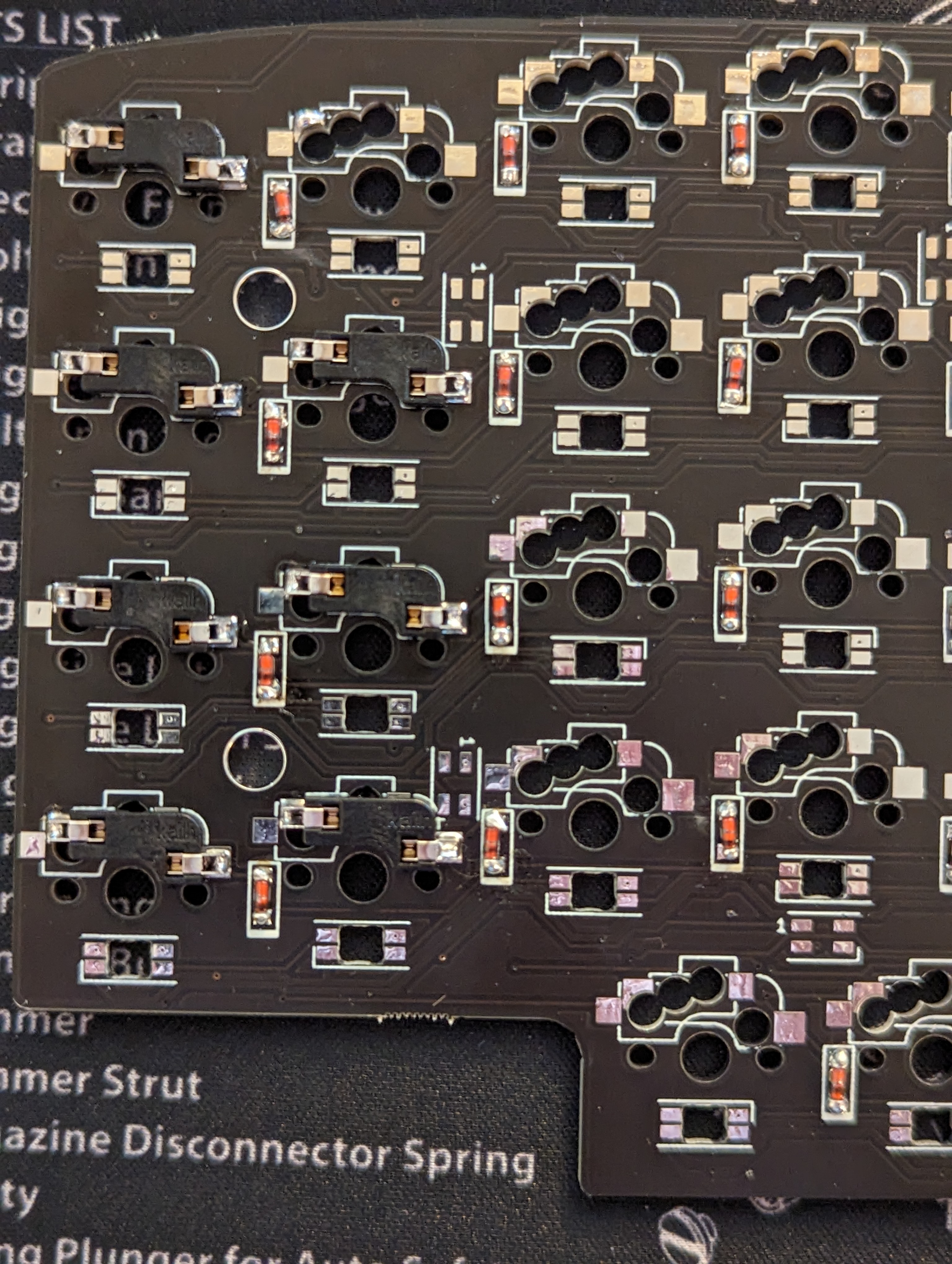
Start by soldering on the diodes. The black bar on the diode should face the same direction as the slightly thicker white bar on the Lulu. See pic:
After the diodes you can solder the switch sockets to the board using the same process I described above.
Be careful to make sure that you solder the socket to the pads matching the ones you bought, Choc sockets get soldered to different pads from the MX sockets. You can refer to my build to see which pads the MX sockets should be soldered to.
Part 4: Soldering the Microcontroller and Misc Parts
Soldering the TRRS jack and reset switch
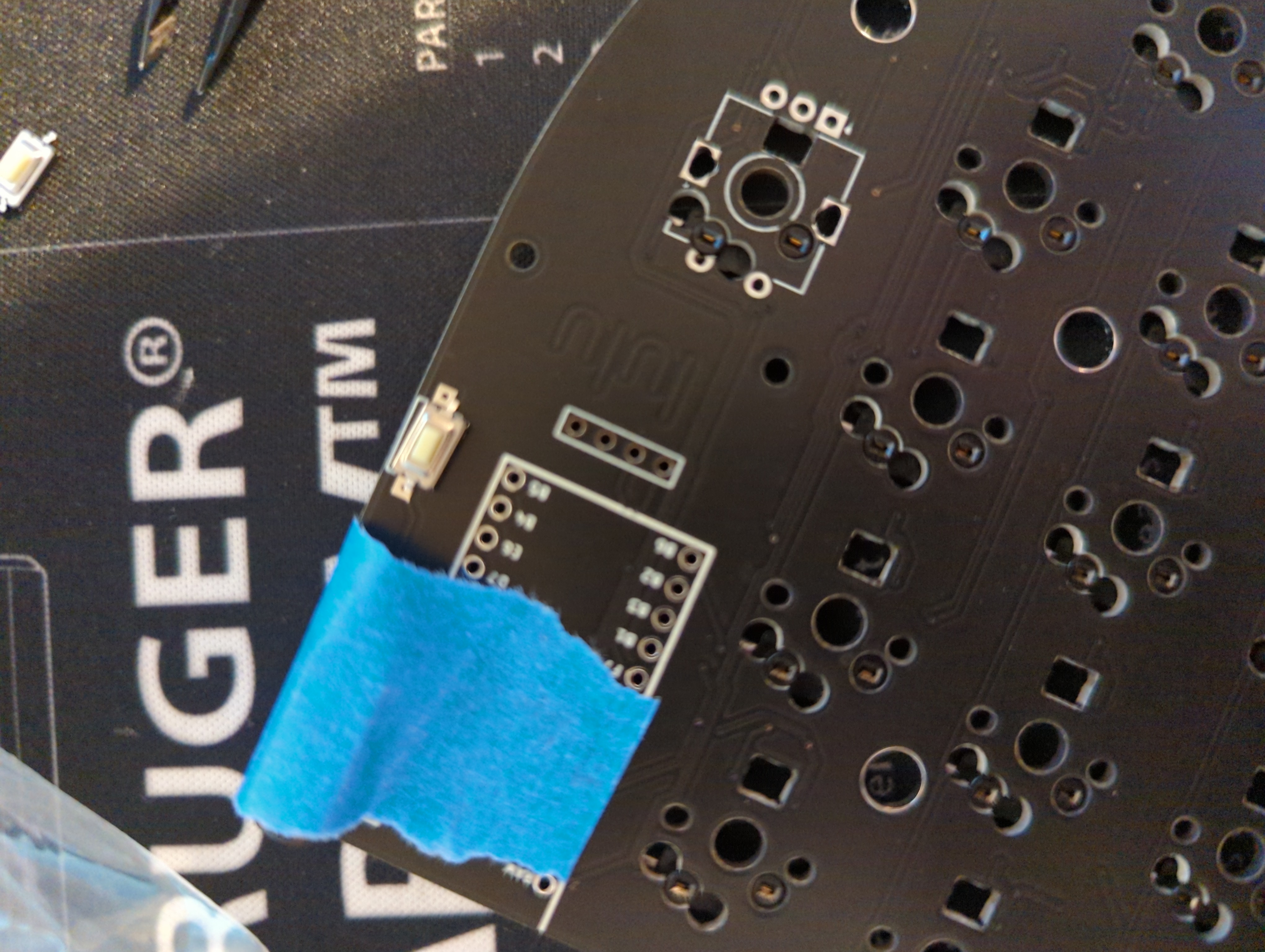
The TRRS jack and the reset switch are mounted on the front side of the PCB (the opposite side from the side that you soldered on the diodes and sockets). Slot the components in and use masking tape to hold them in place. Turn over the board and solder the pins, making sure that the TRRS jack and reset switch are in firm contact with the board.
Install the Blok
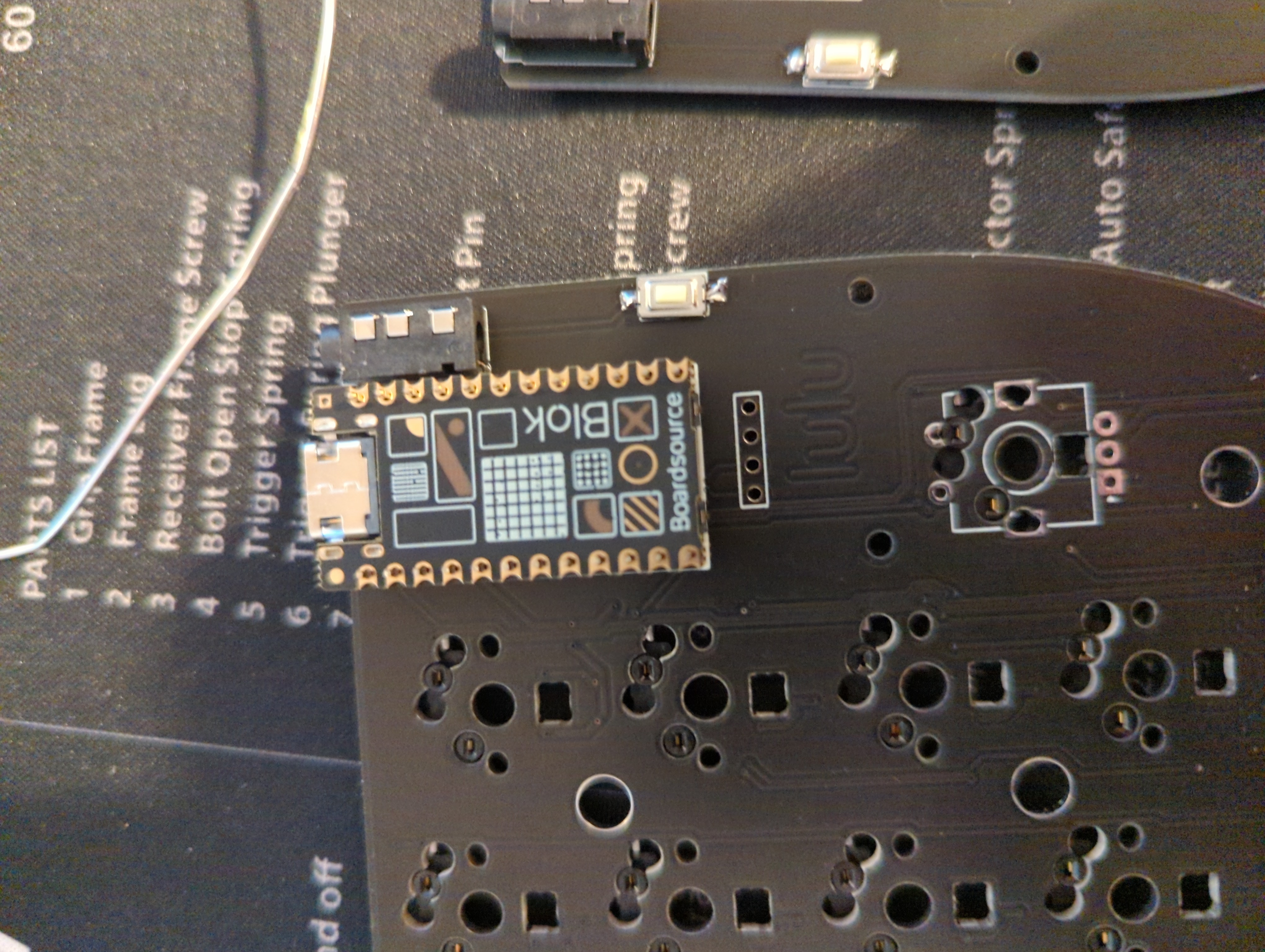
The Blok is installed face down with usb-c port facing the edge of the board:
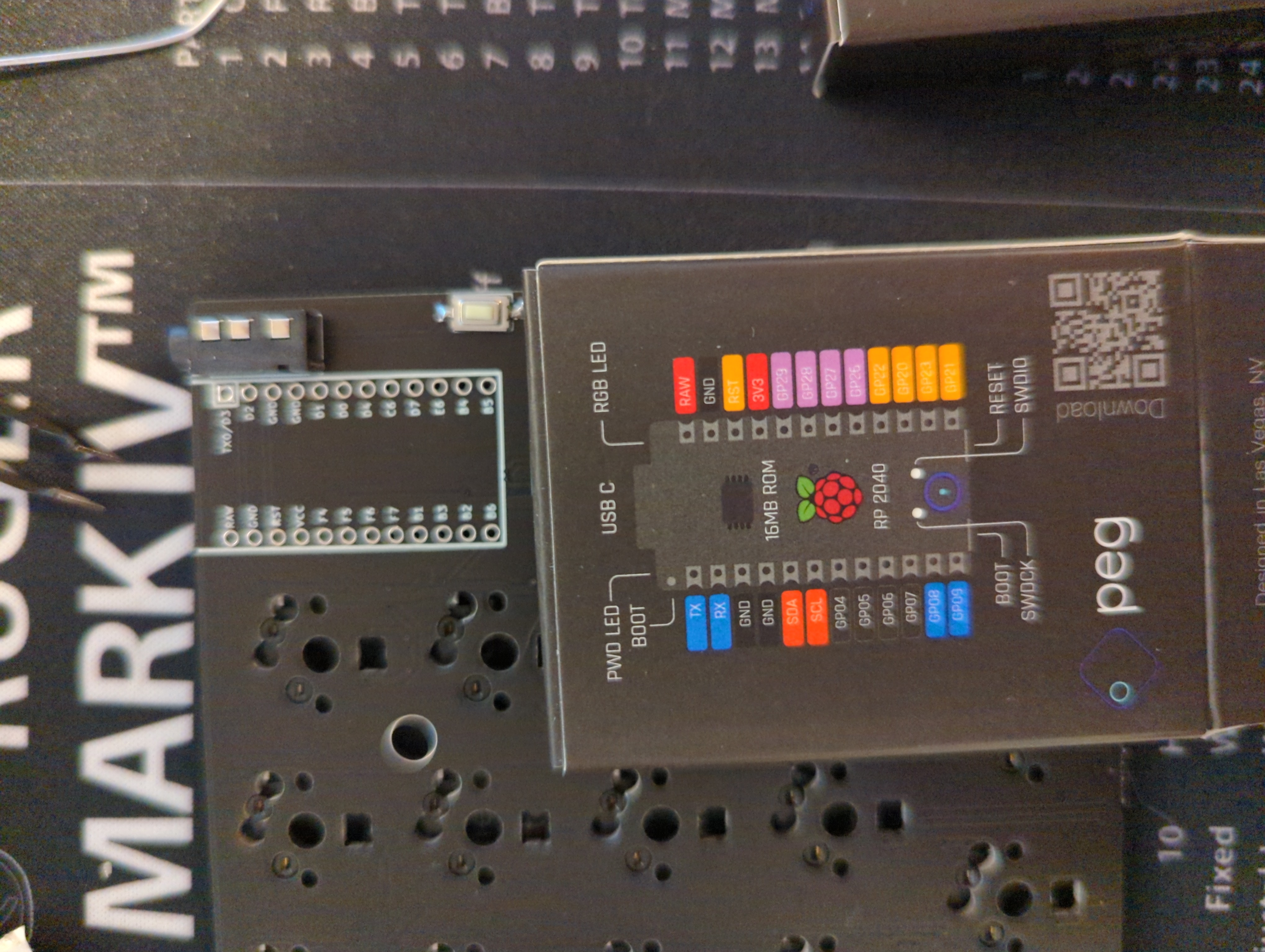 blok pins diagram aligned with board
The guide for installing the pro micro from the Lily58 github may be helpful here as well to ensure that the pins are aligned correctly.
When soldering the pins on the Blok it is important to heat both the pin and the pad and then apply solder from the side. The goal is to get a nice mound of solder cleanly around the pin and on the pad. I ran into a lot of issues here because (as you can see in my pics) my solder job was shoddy and I accidentally bridged some of the pins, so I spent a lot of time re-soldering.
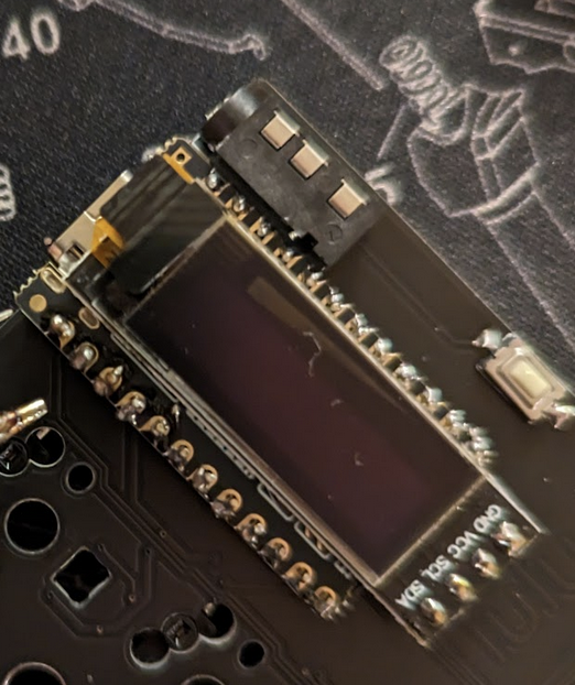
Attach the OLED Display Soldering on the OLED display is very similar to soldering the pins on the Blok. The OLED display itself should lay over the top of the blok.
Attach Spacer Pins
Finally, attach the spacer pins that will be used to mount the clear acrylic protective cover for the Blok and OLED screen. Picture showing these pins is below.
Part 5: Assembling Case and Inserting Switches
After finishing up the last of the soldering you can start assembling the case and inserting switches.
Start by attaching the spacers to the top plate and inserting several switches for spacing - well illustrated in this section of the Lily58 Pro assembly guide on Github.
Insert the switches and spacers into the PCB and press them in, being careful not to bend any of the pins. Once the top plate is attached, attach the rest of the key switches starting from the middle and working out.
Note: be very careful when attaching switches! The pins can bend quite easily, so don’t apply too much pressure unless you are sure the pins are in the holes they should be. It is important to push the switch all the way in, so this will take some practice to get a feel for.
Once all switches are inserted you could attach the back plate and fasten it with screws, but I recommend just setting the PCB on the back plate for now until you’ve flashed firmware and tested the keys. This way if you need to re-solder anything you don’t need to spend extra time disassembling. At this point you could also install the clear acrylic protective cover for the OLED screen and Blok, but I recommend leaving it off until you verify the keyboard is working as expected for the same reason.
Finally, install key caps!
Part 6: Flashing Firmware and Key Map
At this point your keyboard is fully assembled! Now it needs firmware and key maps installed in order for it to function. There are several options when it comes to managing this, but I had a very smooth experience with the Peg software. QMK is generally considered to be the most stable, but I found it very confusing and difficult to set up. Peg is great because it has a convenient GUI and is designed to work well with Blok.
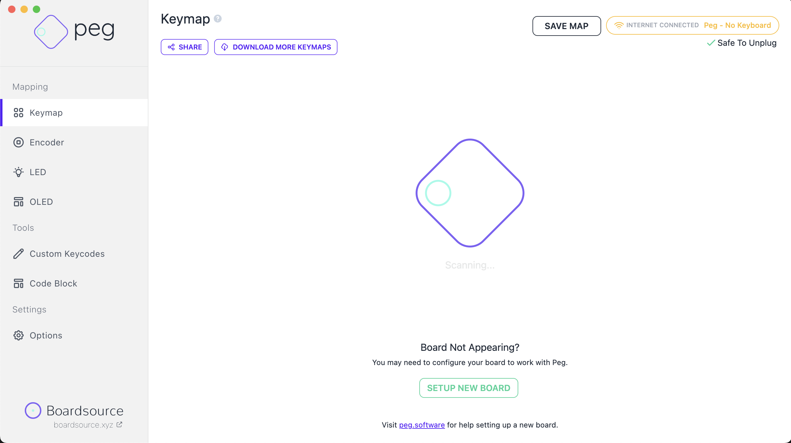
Start by downloading the software from the link above and installing. After that’s done you should open up Peg and plug in your keyboard. Make sure the TRRS cable is plugged into the TRRS jacks on both sides of the keyboard and then plug the USB-C cable into the Blok and into your computer. The keyboard should be mounted as an external drive named LULU by your computer and should be auto-recognized by the Peg software. If it isn’t then you may need to hit the “Set Up New Board” button.
After getting your board connected to Peg you can customize the keymap and led settings to your preference and hit the “Save Map” button in the top left to save it to your keyboard.
Part 7: Testing and Troubleshooting
Done! Your new keyboard should now be fully functional. I recommend starting by pressing each key to ensure that it works. The lily58 pro guide has a few great troubleshooting steps here for what to do when either a single key doesn’t respond or an entire row/column doesn’t respond.
If you run into any further issues I recommend joining the boardsource discord (link below) and checking out the #faq channel as well as the pins in the #hardware-help channel.

